We have made following products for electric panel control. All of this are new in design and easy to operate. Also have a look at their detailed user manual.
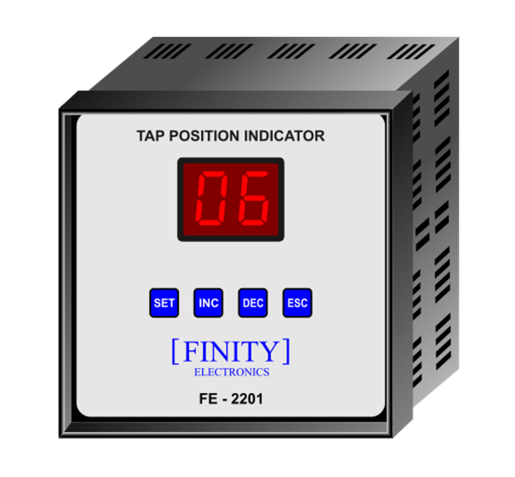
Tap Position Indicator FE - 2201
TPI’s (Tap position indicator) purpose is to read, indicate, count and transmit the present tap, which transformer is working on. From OLTC three output terminals are extended up to TPI named as Max, Com and Min. Following are Technicalities :
Maximum Tap Positions : 35 or user specified ( Auto Tap Detection)
Input Type : Tap Resistance chain or 4-20 mA I/P
Step/Tap Resistance : 10E, 12.5E, 100E, 300E, 1KE (In module programmable by user, refer user manual)
Display : 2-character, 0.56-inch, Bright Red, 7 Segment LED Display.
Supply : Universal Supply, 85-265V AC/DC, 5W
Outputs : 4 / 2 / None, 4-20 mA current loop O/P, optically isolated from measurement system, 700 ohms max load.
RS 485 Output : Available as per user need. ( Refer User Manual )
Panel Cut-Out : 92 X 92 mm
Enclosure Dimensions : 96 X 96 X 85 mm ( H x W x D)
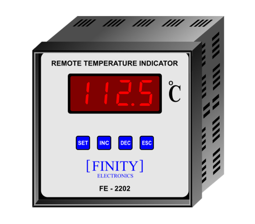
RTI’s (Remote Temperature Indicator) purpose is to read, indicate and transmit the temperature, which transformer winding or oil is at. From the local WTI or OTI three output terminals are extended up to RTI named as Max, Com and Min. Following are Technicalities :
Input Type : Resistive Potentiometer I/P, 4-20 mA current loop I/P (not powered), 4-20 mA current loop I/P self-powered at 24V and Pt-100 temperature sensor I/P.
Resistive Dial I/P : Compatible for 440Ω to 2.8kΩ, or user specified.
Temperature Range : 0.1 °C to 180.0 °C, 0.1 °C resolution, user programmable range in control settings. ( Refer User Manual ).
Display : 4-character, 0.56-inch, Bright Red, 7 Segment LED Display.
Supply : Universal Supply, 85-265V AC/DC, 5W
Outputs : 4 / 2 / None, 4-20 mA current loop O/P, optically isolated from measurement system, 700 ohms max load.
RS 485 Output : Available as per user need. ( Refer User Manual )
Panel Cut-Out : 92 X 92 mm
Enclosure Dimensions : 96 X 96 X 85 mm ( H x W x D)
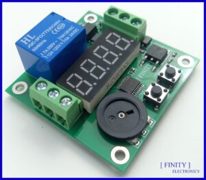
Embedded with a powerful microcontroller for fast & enhanced processing.
24 different modes of operations including: 3 status modes, 14 timer modes, 4 Up-counter modes, 2 Up-counter timer modes, 1 continuous variable pulse mode.
Equipped with first in class dial and switch (SEL) arrangement for easy and flawless selection of modes.
System clock very precisely adjusted with real time. 0.1% error measured.
Has an on-board trigger switch in parallel with the external trigger terminal. Means, mode can be triggered by user from board as well as from any external actuating signal.
Has ability to remember the last used mode with its time setting for all 24 modes. So, no need to set the mode every time you use.
Following are the products which are about to launch soon.
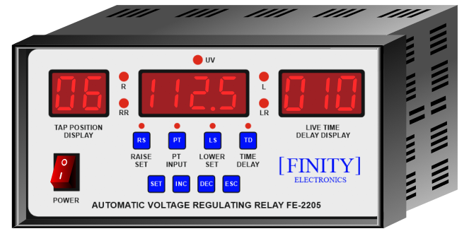
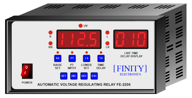
Automatic Voltage Regulating Relay FE-2205
Automatic Voltage Regulating Relay ( AVR ) is a device which is placed in control cubical panel for controlling voltage at secondary side of transformer.
As the load changes at distribution end, line voltage changes accordingly. To keep utility voltage within limits AVR will generate control signal in the form of control pulses. ( Raise and Lower )
The AVR delivers control signal to OLTC, which changes the tap accordingly.
This AVR will be equipped with in built Tap Position Display and the Live Time Delay Display ( used when voltage exceeds preset limits, from 10s to 120s ).
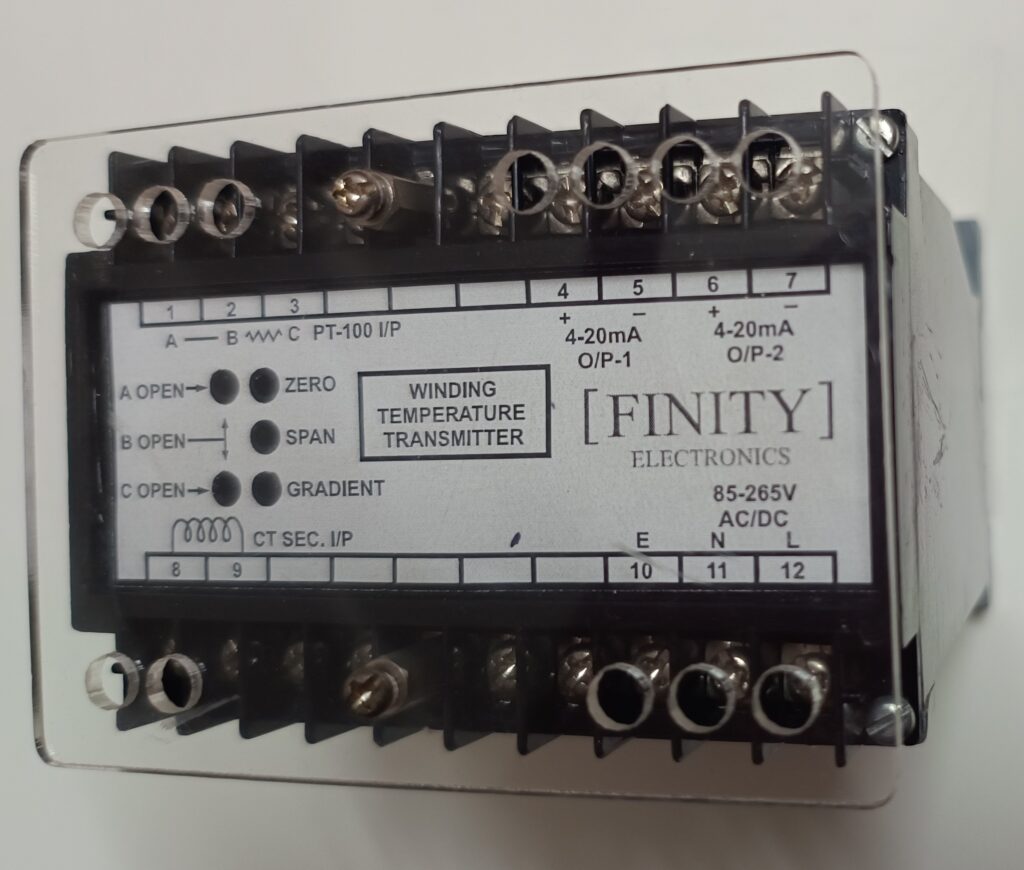
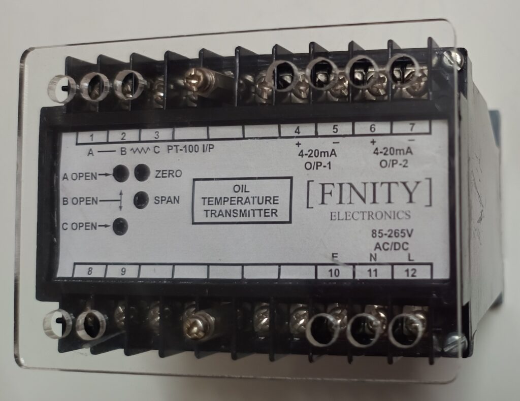
Winding Temperature Transmitter ( WTT ) and Oil Temperature Transmitter ( OTT )
WTT and OTT are a type of CCU ( Current Control Unit ) which transmits the temperature of respective winding or oil of transformer, in the form of a 4-20 mA current loop.
This current is then measured at remote terminal unit ( RTU ) and respective temperature is displayed.
This devices will be equipped with two separate pairs of current outputs and PT-100 and CT sec. inputs for measuring temperature. Also for calibration zero, span and gradient settings will be user trimmable.